|
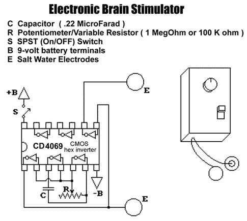
Electronic Brain Stimulator
designed by M.K.ULTRA
![[circuit diagram]](ces_circuit_2.gif)
Parts List:
 C        0.22 microfarad capacitor
 R        1 Megohm Potentiometer
 CD4049   CD4049 CMOS Hex Inverter Integrated Circuit
 E        Salt Water Electrodes:
          (these are made from insulated wire soldered to dimes.
          the dimes are then covered with foam earphone pads, the
          small "ear-bud" variety. Before use these are dipped in
          a salt-water solution to make them conductive, and
          fastened to the head with an elastic terrycloth tennis
          headband.)
 B+,B-    9-volt battery clip.
          (positive & negative terminals, respectively)
 S        SPST (single-pole single throw) on/off switch.

Other Parts:
          A circuit strip or printed circuit board
          solder and a soldering iron
          insulated thin-guage copper wire
          16-pin IC DIP socket (holds the integrated circuit)
          A Knob for the potentiometer
          A circuit or project box to house the unit.
          A 9-volt battery
This rudimentary unit produces biphasic square waves. The current reverses
with each pulse cycle. This helps prevent an ion gradient from building up
across the stimulated tissue. It is suggested that the unit NOT be
used for longer than 20-40 minutes at a session.
NEVER use bare metal electrodes against the skin - these can cause electrolysis burns.
Varying the electrode placement yields different effects. The "standard"
electrode placement is at the mastoid process, the flat, bony area behind
the ears. Alternative electrode sites include the temples near the outside
corners of the eyes (this placement best for phosphene/visual pattern
induction), or one electrode at the center of the forehead and another
at the back of the head near the base of skull/top of neck. The electrodes
may be placed anywhere on the body if one wishes to experiment with
somatosensory stimulation.
Varying the operating frequency (by adjusting the tuning knob) produces
the most striking variety of effects. The texture, brightness and kinetics
of the visual patterns changes remarkably within the 1-50 cycles per second
range. Somewhere above 30-60 cycles per second, visual effects cease.
Brainwave entrainment also occurs at the appropriate settings:
 Delta Waves: .5-3   cycles per second
 Theta Waves:  3-7   cycles per second  (try 4.5)
 Alpha Waves:  7-14  cycles per second  (try 9.5)
 Beta Waves:   14+   cycles per second  (try 14)
The unit can be tuned and calibrated with a frequency meter, but frequency
may drift with operating temperature and battery strength.
Results will vary based on operating conditions, battery strength,
electrode placement, electrode saturation, type of electrode-wetting solution
used individual personal factors and sensitivities, set and setting.
An intensity control may be added by putting a 100K potentiometer in
series with one of the electrode wires.
A trimpot or limiting resistor (about 1K-2.2K ohms) may be put in series
with the frequency-setting potentiometer to adjust the maxiumum frequency.
The unit will stop oscillating if the resistance of R is set below about
1K ohm. This can result in a continuous direct current signal at the
electrodes, which is unsuitable for extended exposure.
A light-emitting diode (LED) can be placed in the circuit to provide
a visual frequency cue. This unit is also capable of driving a pair of
LED-goggles for experimenting with flicker-entrainment.
Alternative Circuits
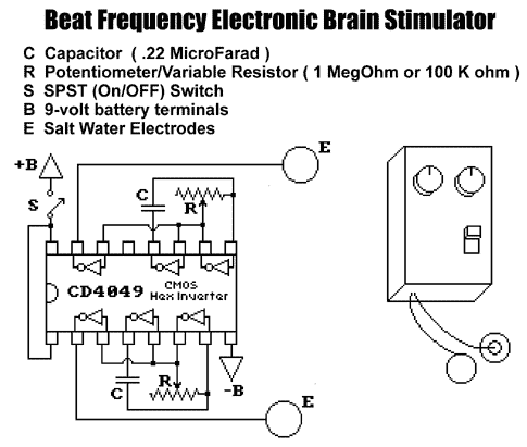
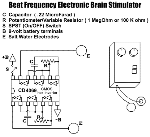
These circuits implement dual oscillators (for multiple frequency/beat frequency effects) or use the CD4069 CMOS Hex Inverter which is a more modern chip and easier to find than the CD4049 chip.

Reader Martin C. has pointed out that there are errors in this diagram. The corrected circuit can be found here. It is likely that other circuits on this page may contain similar errors (particularly the other one based on the 4069 IC). Additional notes and pictures by Martin C.


|